TECHNICAL SPECIFICATIONS
1] Profile Plates &
Stand: The anodized Aluminium profile plate is the basis for training.
All components fit securely & safely onto the profile plate with
safe fixing arrangement.
Grid Dimensions: 50mm, Size: 1000 ×700mm.
2] Shuttle
Valve (OR): 1 No. : The Shuttle Valve is switched through to the output
by applying compressed air to one of the inputs (OR) function. Design
type is OR gate (shuttle valve). Pressure range: (1-10 Bar)
3] Dual
Pressure Valve (AND): 1 No. : The dual-pressure Valve is switched
through to the output by applying compressed air to both the inputs
(AND) Function. Design type is AND Gate (Dual Pressure Valve).Pressure
Range: (1-10 Bar)
4] One way flow
Control Valve Assembly: 1 No. : - The One – way flow control valve is a
combination of flow control valve & a non-return valve. The cross
section of the restrictor can be set by means of a Knurled screw. Design
type is combined flow control Valve. Pressure range – (0.5-10 Bar)
5] Pressure
Sequence Valve assembly: 1 No.:- The pressure of the control signal can
be set by means of the pressure setting screw (variable). Design type is
Poppet Valve with return spring. Operating Pressure range – (1.8 – 8
bar). Control Pressure range - (1 – 8 bar).
6] Single Acting Cylinder: 1 No. : Design type is Piston Cylinder. Operating Pressure 10 bar. Stroke length – Max. 100mm.
7] Double Acting Cylinder: 1 No. : Design – Piston Cylinder. Operating Pressure – 10 bar
Stroke Length – Maximum 100 mm
8] Manifold
Assembly: 1 No. : - Manifold with 6 (2 ×3) Hex-Ball Valve. A common
manifold for plastic tubing allows supply of compressed air to the
control via six individual ports (for plastic tubing PUN 4×0.75)
9] Filter
regulator with Gauge: Filter control valve with pressure gauge, gate
valve, quick push-pull connectors & quick couplings mounted on a
swivel support. The filter with water separator removes dirt, pipe
sinter, rust & condensed water. The pressure control valve regulates
the supply. Air pressure to the set operating pressure &
compensates pressure fluctuations. The filter bowl has a condensate
drain valve. The shutoff valve ventilates & vents entire control.
Input pressure –Maximum (16 bar), Output pressure – Max 12 bar, grade of
filtration– 40 mm approx., Connector – G 1/8 , / PU 4
10] Relay,
Three fold: 2 No. : The device has three relays with terminals and two
buses for power supply. Contact set – 4 change-over switches, Contact
load – maximum 5 A.,
11] Signal
Input, Electrical: 1 No. : The device contains an illuminated
push-button switch (control switch) & two illuminated push buttons
(momentary contact switches) with terminals and two buses for power
supply. Contact set – 2 makes, 2 breaks, and Contact load – maximum 1A.
12] Indicator
& Distributor Unit, electrical –: 1 No. : The device contains an
acoustic indicator and four lamps with terminals and three buses for
power supply. Through-contact socket pairs per lamp allow the element to
also be used as a Distributor.
13] Proximity
switch with attachment: -2 No. : The Proximity switch consists of a
sensor, the mounting kit and the cable. This proximity switch gives a
signal when it detects a metal. The status is indicated by an LED.
Switching Voltage – 24 VDC, Switching current – max. 200 mA, Switching
Power – 6 W approx, switching accuracy - ±0.1mm
14] 3/2
Solenoid Valve, Single with LED,– 1No. : The status is indicated by an
LED on the housing. The valve is equipped with a manual override.
Pneumatic Technical data: Design type is spool valve, pilot controlled
with return spring, Pressure range: 250-800 kPa
(2.5-8 bar), Electrical Technical data: Power consumption – 1.5 W
15] 5/2 way
single Solenoid Valve with LED: 1No. : The status is indicated by an LED
on the housing. The valve is equipped with a manual override. Pneumatic
Technical data: Design type is spool valve, pilot controlled with
return spring, Pressure range: 250-800 KPa (2.5-8 bar), Electrical
Technical data: Power consumption – 1.5 W
16] 5/2
Solenoid Valve, Double with LED: 1 No. : The statuses are indicated by
LEDs on the housings. The valve is equipped with two manual overrides.
Pneumatic Technical Data: Design-spool valve with pilot control,
Pressure range – 150-800KPa (1.5-8 bar)
Electrical Technical Data: Power Consumption – 1.5 W
17] Pneumatic –
Electric convertor:-1 No.: The pneumatic – electric convertor can
fulfil 3 functions: Pressure Switch, Vacuum Switch and Differential
Pressure Switch. Pneumatic Technical Data: Pressure Ranges: Pressure
Switch connector P1 - 0.25 – 3.5bar, Vacuum Switch- -0.2- -0.8 bar
Differential Pressure Switch: Connectors P1….P2 - (-0.95 – 3.5 bar),
Switching Current: - 400 mA.
18] Limit
Switch, Left Actuated – 1 No. : The electrical limit switch comprises a
mechanically operated micro switch. When the roller lever is pressed,
for example, by control cam of a cylinder, the micro-switch is actuated.
The circuit is closed or opened via the contacts. The micro-switch can
be wired as a normally open or normally closed or changeover contact.
Contact load: maximum 5A, switching frequency – maximum 200Hz,
Reproducible accuracy – 0.2mm, Switch travel – 2.7 mm, Actuator force –
5N
19] Limit
Switch, Right actuated – 1 No. : The electrical limit switch comprises a
mechanically operated micro switch. When the roller lever is pressed,
for example, by control cam of a cylinder, the micro-switch is actuated.
The circuit is closed or opened via the contacts. The micro-switch can
be wired as a normally open or normally closed or changeover contact.
Contact load: maximum 5A, switching frequency – maximum 200Hz,
Reproducible accuracy – 0.2mm, Switch travel – 2.7 mm, Actuator force –
5N
20] Equipment
Tray – 1 No. : MS powder coated tray with slots for placing components
to be supplied with Electro-pneumatic supplementary kit.
21] Power
Supply Unit – 1 No.: Input Voltage - 230/115 V Ac (47-63 Hz.), Output
Voltage – 24 V DC, short circuit proof, output current – Max. 4.5 A,
Connection Cable – 3m
22] Plug in adapter: For mounting components with plug-in foot on the aluminium profile plate.
23] Quick Push-Pull connectors: Sufficient shall be supplied for branching of the tubing for making of the circuitry.
24] Plastic Tubing: PUN 4×0.75, Exterior Diameter-6mm, Interior Diameter- 4mm, Transparent – 10mtrs, Blue-10mtrs.
25] Set of moulded Cables:
1.5 Meter (2 core) ________________6 No.
1 Meter (3 core) _________________ 3 No.
300 mm Red: - 06 No.
300 mm Black: - 06 No.
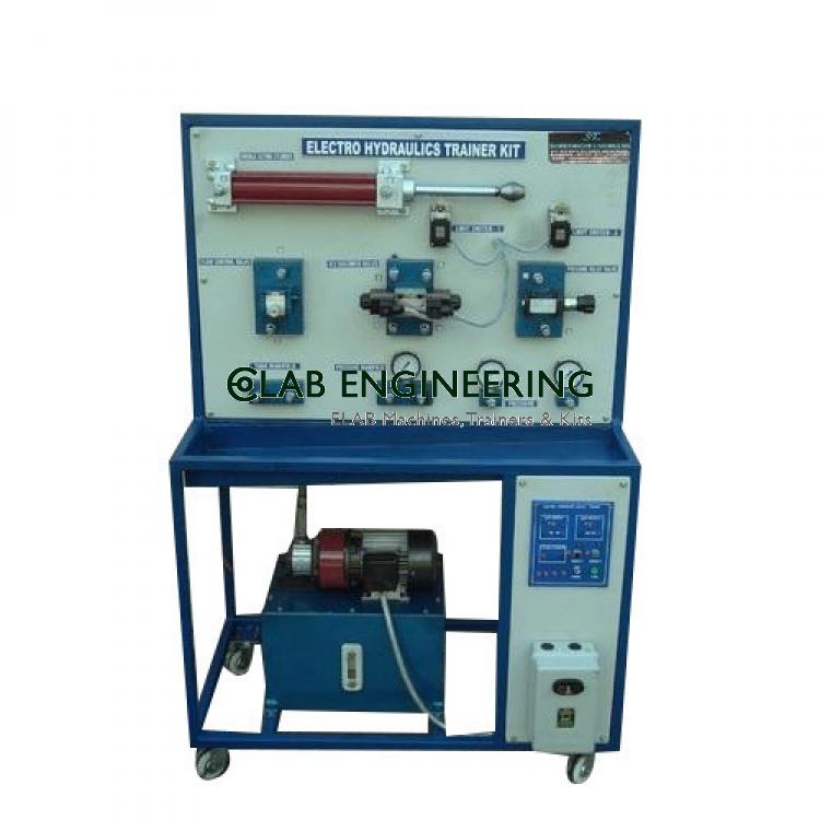
Range Of Experiments:
Study of Advanced Electro – Pneumatic Trainer
Study of various Pneumatic Components
Study of Pneumatic & Electro-pneumatic Circuits
Services Required:
230 V AC, 50 Hz Power Supply.
Dry, Compressed, Clean Air supply at 4-5 Kg/Cm².
Note: All descriptive matter and illustrations are intended to give only a general idea of the equipment. Detailed specifications may be altered at the company’s discretion without any notice.
Similar items like ELECTRO-PNEUMATIC TRAINER KIT you may view
ELAB Engineering is a leading manufacturer, supplier and exporter of electro-pneumatic trainer kit and a complete range of engineering laboratory and technical training equipment. We supply high-precision, lab-grade instruments in bulk to engineering colleges, universities, technical institutes and industries across 55+ countries — with competitive tender pricing, full export documentation and reliable after-sales support.
As a leading manufacturer, supplier and exporter, we deliver tender-grade quality with documented compliance to institutions, laboratories and training facilities across 55+ countries.
Every unit is manufactured to international quality standards and tested before dispatch, with QC documentation and calibration certificates included.
Established export channels across Africa, Asia and the Middle East, with complete shipping documentation, certificates of origin and customs paperwork.
We offer customisation for tender specifications, OEM branding, voltage variants and bulk institutional orders to match your exact requirement.
Technical consultation before purchase, installation guidance, operator training documentation and responsive after-sales support from our team.
Trusted by institutions, governments and industries worldwide for reliable, tender-documentation-ready supply.
Practical laboratory training & coursework experiments
STEM education & physics / chemistry / biology demos
Process quality, testing & calibration requirements
Clinical lab, diagnostics & pathology applications
Ministry, defence research & PSU lab infrastructure
UNICEF, WHO, UNDP & bilateral aid procurement
Skill development & technical training labs
Direct & sub-contractor tender fulfilment
ELAB Engineering is a recognised manufacturer, supplier and exporter of ELECTRO-PNEUMATIC TRAINER KIT. We supply this product across our complete export network — from individual institutional purchases to large-scale tender supply contracts.
All shipments include complete export documentation, customs paperwork & freight handling.
Request a custom quote, full technical datasheet, or place a bulk / tender enquiry. Our specialists respond within 1 business day with pricing, lead time and export documentation.
Common questions from buyers, procurement officers and technical evaluators about ordering, customisation, lead time and documentation.


-lab-577644737.jpg)
-lab-837957510.jpg)